220 V AC LED Chaser Circuit

Light Chaser is a circuit where 1 LED light is switched on after another LED. That’s mean Leds are chasing each other. This is Very easy 220 V AC LED Chaser Circuit Diagram.

This 3 Channel Light Chaser Circuit is mainly made of 2 ICs, 555 timer IC & 4017 Counter IC. Using these components we can decorate with forward & reverse wave only.

You can modify this circuit from 3 Channel to 10 Channel its very easy i will explain every thing to you in this ( 220 V AC LED Chaser Circuit Diagram) Article.

220 V AC LED Chaser Circuit Diagram

The 3 Channel Light Chaser Circuit works with two ICs, 4017 & 555. The 555 Timer IC sends a clock pulse to the 4017 Counter IC. The counter IC counts and sends a signal to the next output pins. There are a total of 16 pins in the 4017 IC. out of them, 10 pins are output pins. When it completes 10 counting’s, it again counts from 1st pin

Click Here To Buy
220 v ac led chaser circuit

Parts List

  1. Timer IC 555 1pc
  2. IC 4017 1pc
  3. Transistor Q1-Q3, BC547/BC548 or any NPN Transistor 3pc
  4. Diode D1-D3 1N4007 3pc
  5. Capacitor 10uf/25v 1pc
  6. Resistor R1 (VR1) 100K 1pc
  7. Resistor R2 10k 1/4watt 1pc
  8. Resistor R3-R5 1k 1/4watt 3pc
  9. Relay RL1-RL3 12volt 
  10. Connector 2 Terminal 1pc,  4 Terminal 1pc
  11. 12 volt DC Power Source

220 V AC LED Chaser Circuit Diagram Working

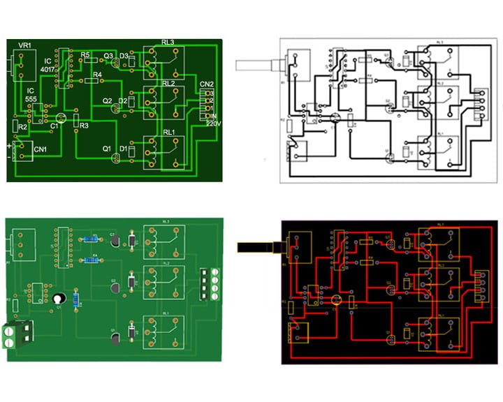
This Circuit is based on Timer IC555 & IC4017. The 555 Timer IC sends a clock pulse to the 4017 Counter IC. The counter IC counts and sends a signal to the next output pins. There are a total of 16 pins in the 4017 IC. out of them, 10 pins are output pins (Output Pin No. 3,2,4,7,10,1,5,6,9,11) and pin no 15 is Reset pin. When it completes 10 counting’s, it again counts from 1st pin.

But in this circuit we are using only 3 output pins Pin no 3,2 and 4 and reset the 4th output pin no 7 with IC Reset Pin (Pin No. 15).With same method you can use output pins as per your need. Example if you need 6 channel chaser you can use pin no 3,2,4,7,10,1 as output pins and reset pin no 5 with pin no 15. You can make 3-10 output led chaser lights as per your need just changing the reset pin connection.

IC 555 & IC4017 Pinout

IC 4017 Pinout , IC555 Pinout

This Touch Switch Circuit Diagram is built around a 555 timer by making use of the default properties of the Pins of the 555 Timer IC. With the help of this circuit, you can turn ON and OFF a device by simply touching the……. Read More

How LED Chaser Lights Works With 220 Volt AC

Here we are using 12 volt Relay for this purpose you can see in circuit diagram. Use relay according to your need Because AC Load is depends on Relay amperes 

PCB Layout For 220 V AC led Chaser Circuit Diagram

The image below you can take print with your printer on A4 size paper no need to worry about PCB Size its automatically fixed and you can make your simple PCB on Vero Board Watch Video For Details
220 v ac Chaser PCB Layout

Watch Video:- How To Make LED Chaser Circuit Diagram

error: Content is protected !!
Scroll to Top