Automatic 12v Portable Car Battery Charger Circuit Diagram
This is the very simple Automatic 12v Portable Car Battery Charger Circuit Diagram. The IC 555 is so versatile, that it can be considered the single-chip solution for all circuit application needs. No doubt it’s been utilized here too for yet another useful application.
A single IC 555, and a handful of passive component is all that’s needed for making this outstanding, fully automatic lead acid battery charger circuit.
The proposed design will automatically sense and keep the attached battery up to date.
Automatic 12v Portable Car Battery Charger Circuit Diagram
The battery which is required to be charged may be kept connected to the circuit permanently, the circuit will continuously monitor the charge level, if the charge level exceeds the upper threshold, the circuit will cut off the charging voltage to it, and in case the charge falls below the lower set threshold, the circuit will connect, and initiate the charging process.

Parts List For Car Battery Charger Circuit With IC 555
- IC 555 1pc
- Diode 1N4007 2pc
- Diode 10amp 1pc
- Zener Diode 5.1 volt 1watt 1pc
- LED Green & RED 1pc each
- Relay 12 volt 10amp 1pc
- Capacitor 220uf/25v 2pc
- Variable Resistor 50K 2pc
- Resistor 1k 1/4watt 2pc
- 2 Terminal Connector 2pc
- Vero Board
How To Adjust The Automatic Battery Charger Circuit
Connect a variable power supply source across the battery points of the circuit. Watch Video For Details
Apply a voltage that may be exactly equal to the desired low voltage threshold level of the battery, then adjust VR1, such that the relay just activates.
Next, slowly increase the voltage up to the desired higher voltage threshold of the battery, adjust VR2 such that the relay just deactivates back.
The setting up of the circuit is now done.
Remove the external variable source, replace it with any battery which needs to be charged, Now Just Give it 15 Volt 10 AMP DC Power as Input if You want to Charge Car Battery.
Rest will be automatically taken care of, that is now the battery will start charging and will cut off when its fully charged, and also will get connected to power automatically in case its voltage falls below the set lower voltage threshold.
This is The Best Automatic 12v Portable Car Battery Charger Circuit Diagram
This battery charger circuit provides the Automatic cut off the facility when the battery gets fully charged. Before the use of this circuit, you need to adjust the Cut off voltage range for the auto cut. Read More…..
Charging Voltage and Ampere For Automatic Battery Charger Circuit
The power supply section is an ordinary bridge/capacitor network.
The diode rating will depend on the charging current rate of the battery. As a rule of thumb the diode current rating should be twice that of the battery charging rate, while the battery charging rate should be 1/10th of the battery AH rating.
It implies that TR1 should be around 1/10th of the connected battery AH rating.
The relay contact rating should be also selected as per the ampere rating of Power Supply.
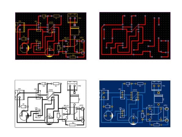
PCB Layout For Automatic 12V Battery Charger Circuit
You Can Take Print Of this PCB Layout on A4 Size Paper and make This Circuit on Vero Board like My video Please Watch Video For Demo and Details

How This Automatic Battery Charger Circuit With IC 555 Works
Here the IC 555 is configured as a comparator for comparing the battery low and high voltage conditions at pin#2 and pin#6 respectively.
As per the internal circuit arrangement, a 555 IC will make its output pin#3 high when the potential at pin#2 goes below 1/3 of supply voltage.
The above position sustains even if the voltage at pin#2 tends to drift a little higher. This happens due to the internal set hysteresis level of the IC.
However if the voltage continues to drift higher, pin#6 gets hold of the situation and the moment it senses a potential difference higher than 2/3rd of supply voltage, it instantly reverts the output from high to low at pin#3.
In the proposed lead acid battery charger circuit design, it simply means that, the presets VR1 and VR2 should be set such that the relay just activates when the battery voltage goes below say 13V (You can Voltage according to your need) and deactivates when the battery voltage reaches above 14.4V.

