Touch Switch Circuit Diagram with IC555
This Touch Switch Circuit Diagram is built around a 555 timer by making use of the default properties of the Pins of the 555 Timer IC. With the help of this circuit, you can turn ON and OFF a device by simply touching the Touch Plates or Wire
And the important feature of this circuit is that you will not get any electrical shock which we sometimes get while using the normal switches, even though we are using touch plates.
Touch Switch Circuit Diagram
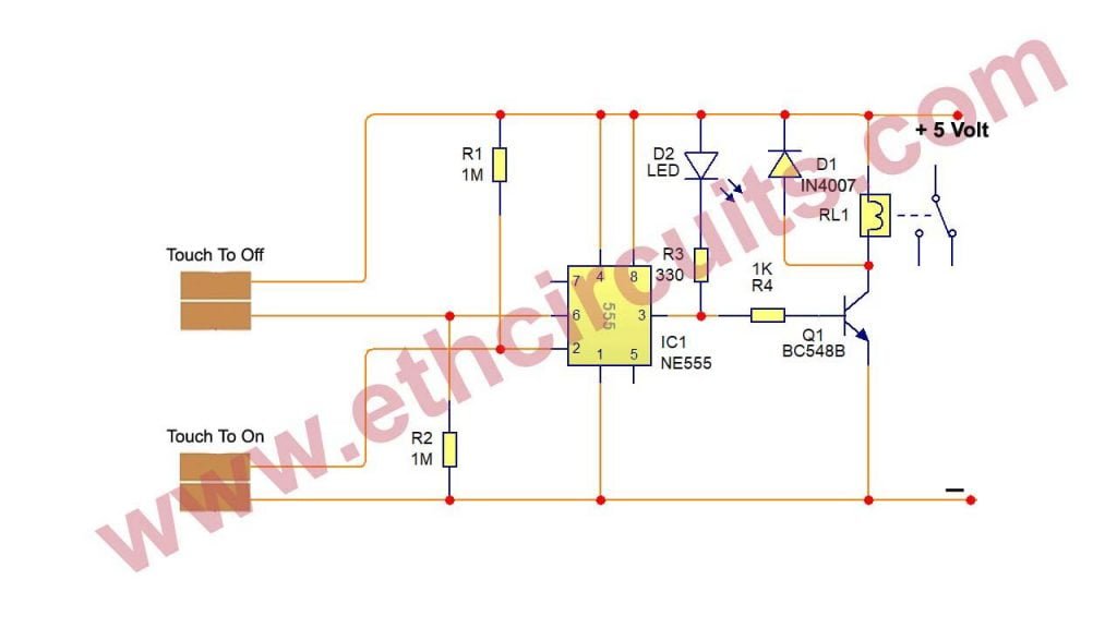
The circuit diagram for the touch ON and OFF switch circuit is shown in the below image.

A touch switch is a type of switch that only has to be touched by an object to operate. It is used in many lamps and wall switches that have a metal exterior as well as on public Continue Reading…..
Parts List For Touch Switch Circuit
- IC 555 1pc
- Transistor BC548/BC547/2n2222 or any NPN transistor 1pc
- LED 3mm/5mm any color 1pc
- Relay 5V 1pc
- Diode IN4007 1pc
- Resistor 1mega 2pc, 1k 1pc, 330 Ω (All resistor 1/4 watt)
How To Make The Touch Switch Circuit
The design of the Touch Switch Circuit Diagram is very simple. First, the GND, VCC and RST pins of the 555 i.e. pins 1 is connected to GND and Pins 8 and 4 with +5V . Pin 2 is pulled HIGH using a 1 MΩ Resistor and Pin 6 is pulled LOW using a 1 MΩ Resistor.
Two touch plates are connected to pins 2 and 6 as shown in the circuit diagram. In case of the touch to ON plate, one end is connected to pin 2 and other end is connected to GND. Similarly, one end of the touch to OFF plate is connected to +5V and the other end is connected to Pin 6.
How Touch Switch Circuit Works
Connect the circuit as per the circuit diagram and apply the 5 volt . To turn “ON” the device, touch the “ON” plate with your finger and to turn OFF the device , touch the OFF plate.
When power supply is applied to circuit, the device connected through the relay (we have connected a light bulb) remains OFF. Now, if we observe the circuit diagram, Pin 2 is pulled HIGH and Pin 6 is Pulled LOW.
When we touch the ON plate, voltage at Pin 2 (Trigger Pin) of the 555 IC becomes LOW. As Pin 6 is already LOW, the output at Pin 3 becomes HIGH. Since this is connected to the Relay Module through the Transistor, the Transistor will be turned ON and it in turn activates the Relay. As a result, the device gets switched ON.
At this point voltage at pin 6 is zero as it pulled LOW by default and voltage at Pin 2 is HIGH. Now, when you touch the OFF plate, the Pin 6 is supplied with +5V for a brief time and as a result, the output of the 555 Timer IC will become LOW. This will turn off the transistor and also the relay. Hence, the device will be switched OFF.
Principle Behind The Project
The main principle behind the project lies in the basic functionality of the pins of 555 Timer. We know that 555 Timer has 8 pins namely GND (1), Trigger (2), Output (3), Reset (4), Control Voltage (5), Threshold (6), Discharge (7) and VCC (8).
In this, Pins 2 and 6 are used in this project. Now, we see the basic working of these pins. When Pin 6 i.e. the Threshold pin is held LOW, and if Pin 2 i.e. the Trigger Pin is made LOW, the output of the 555 Timer IC will be HIGH and it stays there. This condition can be used to turn ON the appliance.
Now consider Pin 2 is pulled HIGH and if Pin 6 is made HIGH, the output of the 555 Timer IC will be LOW and it stays there. This condition can be used in our project to turn OFF the load or device.


