Whats Is Automatic Water Pump Controller Circuit Diagram
Automatic water Pump controller is a product made to automatically control the water level in water tank, which helps ensure constant water retention in the storage tank. This automatic water level controller is used to automatically fill the water tank when it is empty or below the fixed water level.
Automatic water level controller turn on the Pump Motor whenever the water level drops below a certain level and shuts off the motor when the water rises above the set level.
Automatic Water Pump Controller Circuit Diagram

Advantages of Automatic Water Level Controller
- Automatic water level controllers can maintain an exact preset water level.
- It can be installed in homes, hotels, and hospitals.
- The power used by this controller is low and negligible.
- It can be installed in metro cities where the drinking water is the only water used for all purposes, which keeps the drinking water from being wasted.
- These controllers are compact, easy to installed, and easy to move.
- The sensor can be free of corrosion and the maintenance cost is very low.
I am using two different circuits for this. I made the Water Level Indicator circuit with IC ULN 2003.2nd circuit for Pump Control made with IC555. This circuit will off the pump when Tank is Full and you set up the Water Level where you want to ON the pump again Continue Reading…..
Relay Connection For Pump

Parts List For Automatic Water Pump Controller Circuit Diagram
- IC ULN – 2003
- Resistor 100 ohm 1/2 Watt
- Resistor 22K – 2 Pc
- Resistor 1M – 2 Pc
- Resistor 1K – 1 Pc
- Resistor 220K – 1Pc
- Resistor 470Ohm – 1Pc
- Diode IN4007 – 1Pc
- Transistor BC547
- Relay 6V – 1 Pc
- Capacitor 104 PF
- LED – 1 Pc
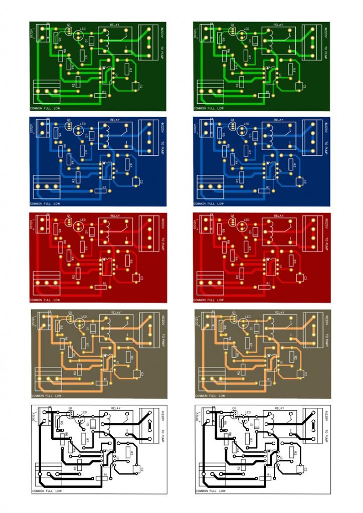
PCB Layout For Fully Automatic Water Pump Controller
You can Download PCB Layout From Link Below and Print on A4 Paper and paste it on Vero board and assemble your circuit very easy you can watch my other videos for how to make simple PCB with this Print method or you can download Gerber File from link below


