How To Make Automatic Street Light Controller Circuit Diagram
Have you ever wondered how street lights automatically turn on at night and automatically off in the morning? Is anyone going to TURN ON/OFF these lights? There are a few ways to turn on street lights but the following circuit describes the Automatic Road Light Control Circuit that uses LDR perform this function automatically.
The circuit diagram here is that automatically switches on at night and then shuts off when the sun rises. In fact you can use this circuit to make any type of automatic night light. In This article you can learn How to make automatic street light controller circuit at home.
Automatic Street Light Controller Circuit Working
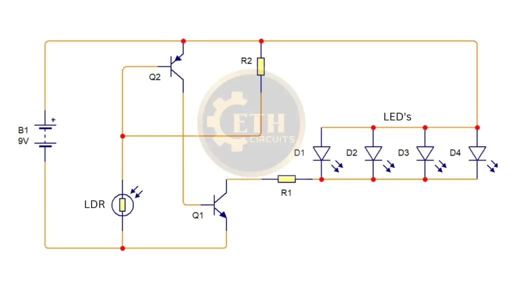
The circuit uses a Light Depended Resistor(LDR) to sense the light . When there is light the resistance of LDR will be low. So the voltage drop across the Resistor R2(100K) will be high. This keeps the transistor Q2(BC557) OFF. The collector of Q2 is coupled to base of Transistor Q1(2N2222). So Q1 will be OFF and so do the LED will remain OFF.
When night falls the resistance of LDR increases voltage drop across the Resistor R2 will be Low and Resistor R2 gives the voltage to Transistor Q2’s Base and Transistor will on. This makes transistor Q2 ON which in turn makes Q1 ON. The LED’s will glow.
Automatic Street Light Controller Project Circuit With LED

Parts List of Automatic Street Light Controller Circuit
- Q1 Transistor 2N2222 or you can use any NPN High ampere Transistor according to your Load
- Q2 Transistor BC 557 or any General purpose PNP Transistor
- LDR ( Light Depending Resistor)
- R2 100k 1/4watt or you can use 100k To 250k variable Resistor for adjustment
- R1 10 ohm 1/2 or 1watt
- White Color LED 1-10 pc
Automatic Street Light Controller Circuit With LDR and Relay
Here you can find automatic street light controller circuit with LDR and Relay with the help of this circuit you can operate any 220 volt BULB

Automatic Street Light Controller Circuit Working with Transistor and LDR
LDR or Photoresistor is a sensor here and Resistance Variation Converted to Relay switch Open and Close position using two transistors. LDR is connected between bias lines via the Variable Resistor VR and we can change the LDR sensitivity level by changing the Variable Resistor value. The base of the Transistor Q1 is connected to the LDR connection with the Variable Resistor. The Q1 transistor output is connected to the base of the Q2 transistor.
The 12V Relay is connected to the Q2 collector terminal, where the Q2 transistor acts as a Switch to make the Relay coil open and close by connecting to the bias. Diode D1 protects the transmitted coil back eg. In the Relay Normal Open (N / O) 230V bulb terminal is connected and another bulb terminal is connected to AC supply (neutral) and the AC supply phase is connected to the Relay Common terminal. When the Relay coil receives power the N / O terminal connects to the normal terminal and the bulb goes on.
When sunlight falls on the LDR it becomes a strong resistance factor and allows bias to emerge on the Q1 base and Q1 to turn ON so there is no bias on the Q2 base so Q2 stands in a closed position. If there is no light on the LDR it becomes a High resistance and there is no bias from Q1 base, which is why Q1 is CLOSED and then bias from R1 appears on the Q2 base and then OPEN which is why the Relay coil receives supply and on and Make (N / O) contact closed and bulb glow.
Parts List For Street Light Controller Project Circuit
- Transistor Q1-Q2 BC547/2N2222 or general Purpose NPN Transistor
- LDR 1pc
- R1 1K 1/4watt, VR 100k
- Diode D1 1N4007
- Relay 12Volt
- You can use Terminal Block For DC Input And for 22o Volt AC or you can connect without Terminal Block
