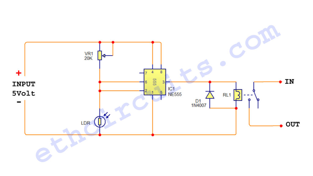
LDR Circuit Diagram With Relay

In today’s article, we will explore an exciting project involving an LDR circuit diagram with relay. This project is not only simple to understand but also helps you grasp the basics of electronics. By the end, you will know how to create a light-dependent resistor (LDR) circuit that can control a relay.
What is an LDR?
Before diving into the LDR circuit diagram with relay, let’s first understand what an LDR is. An LDR, or light-dependent resistor, is a type of resistor that changes its resistance based on the amount of light falling on it. When light is bright, the resistance is low; when it’s dark, the resistance is high. This property makes LDRs useful in various applications, such as automatic street lights, light-sensitive alarms, and more.
Components Required for the LDR Circuit
Components Overview
- LDR (Light Dependent Resistor): A resistor that changes its resistance based on the light intensity. It has low resistance in bright light and high resistance in darkness.
- 555 Timer IC: Configured as a comparator in this circuit.
- Relay: A switch that allows you to control a larger load (like a light) using a small signal.
- Diode (1N4007): Protects the circuit from back EMF generated by the relay coil.
- 20K Potentiometer (Preset): Used to adjust the sensitivity of the LDR.
Circuit Explanation
Power Supply: You are using a 5V mobile charger to power the circuit.
LDR and Potentiometer: The LDR is connected in series with the 20K preset resistor. The voltage across this combination varies depending on the light levels:
- Daytime: In bright light, the resistance of the LDR is low, resulting in a higher voltage at the junction between the LDR and the potentiometer. This voltage is fed to pin 2 (trigger) of the 555 timer.
- Nighttime: When it gets dark, the resistance of the LDR increases, lowering the voltage at the junction.
555 Timer Configuration: The 555 timer is configured in a comparator mode:
- Pin 2 (Trigger): Receives the voltage from the LDR/potentiometer.
- Pin 3 (Output): Controls the relay.
- Pin 6 (Threshold): Connected to pin 2 to set the reference voltage.
Operation:
- Daytime: When the ambient light is high, the voltage at pin 2 is above the threshold (set by the potentiometer), keeping the output (pin 3) low. This means the relay is off, and any connected load (like a lamp) is not powered.
- Nighttime: When the light level drops, the voltage at pin 2 falls below the threshold, causing the output at pin 3 to go high. This energizes the relay, closing the switch and powering the connected load.
Diode: The diode (1N4007) is connected in parallel with the relay coil (cathode to the positive side). It prevents back EMF (a voltage spike generated when the relay coil is de-energized) from damaging the 555 timer or other components.
Summary
In summary, this circuit automatically turns on a device (like a lamp) at night by detecting low light levels through the LDR and adjusting its sensitivity with the potentiometer. The relay acts as a switch controlled by the output of the 555 timer, and the diode protects the circuit from voltage spikes.
If you have any specific questions about the circuit or need further details, feel free to ask!
Circuit Diagram

Testing the Circuit
After assembling the circuit based on the LDR circuit diagram with relay, it’s time to test it:
- Power Up: Connect the power supply to your circuit.
- Light Condition: Shine a light on the LDR. If everything is connected correctly, the relay should deactivate, turning on the connected load.
- Dark Condition: Cover the LDR to simulate darkness. The relay should activate, turning off the load.
Applications of the LDR Circuit with Relay
The LDR circuit diagram with relay can be used in various applications:
- Automatic Street Lights: Lights that turn on when it gets dark.
- Light-Activated Alarms: Systems that activate when a certain light threshold is crossed.
- Home Automation: Control home appliances based on ambient light conditions.
Troubleshooting Tips
If you encounter issues while building your LDR circuit diagram with relay, consider the following troubleshooting tips:
- Check Connections: Ensure all components are connected correctly as per the circuit diagram.
- Verify Component Functionality: Test the LDR and other components with a multimeter.
- Inspect Power Supply: Ensure your power supply is working and providing the correct voltage.
- Relay Check: If the relay doesn’t activate, try swapping it with another relay to ensure it isn’t faulty.
Conclusion
In this article, we covered the essentials of creating an LDR circuit diagram with relay. We discussed the components needed, how the circuit works, and how to assemble it step-by-step. This project not only helps you understand the behavior of LDRs and relays but also serves as a foundation for more advanced electronic projects.
With this knowledge, you can start experimenting with different applications of LDR circuits and even improve your circuit designs. Happy building!

