Blown Fuse Indicator Circuit Diagram

A fuse is an electrical safety device that provides overcurrent protection of an electrical circuit. Its essential component is a metal wire or strip that melts when too much current flows through it, thereby interrupting the current.

It is a sacrificial device; once the fuse is blown, the circuit is open and must be replaced or rewired, depending on the type. In general, when the device signals a power failure, the cause may just be a blown fuse.

Here is a blown fuse indicator circuit that shows the fuse status via LEDs. This compact circuit is very useful and reliable. It uses very few components, which also makes it cheap.

blown fuse indicator circuit diagram

Simple Blown Fuse Indicator Circuit Diagram

blown fuse indicator circuit

Parts List

  1. LED Red 1Pc, Green 1Pc
  2. Resistor 47k To 100k any 1/4watt or 1/2watt 2pc
  3. Small wire

How Blown Fuse Indicator Circuit Works

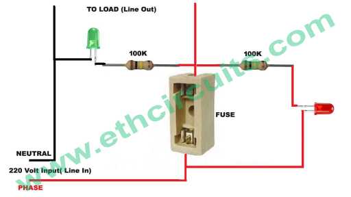
A simple blown fuse indicator circuit a only a resistor and Red LED connected in series and then in parallel with the target fuse. When we apply AC power to the load through this fuse and circuit setup, because of the low resistance in the fuse wire, current flows through it easily and no current flows through the resistor and the LED, so the LED remains in the OFF state.

Click Here To Buy

If for some reason the fuse is blown, then no current flows through the open fuse, then here the current flows only through the resistor and the LED, so the LED starts to glow (that is, it lights up), which means that the fuse is blown.

And the second Green Led Directely Connected to the Netural wire and with phase wire after the fuse. when fuse is ok Green Led will be in on position

error: Content is protected !!
Scroll to Top