What Is Clap Switch ?
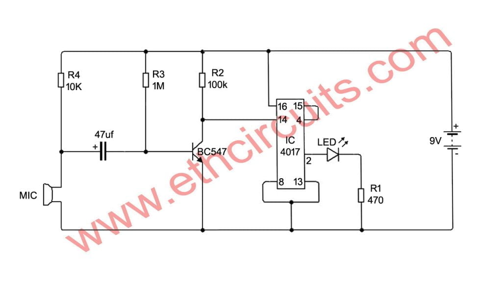
Clap switch is an interesting hobby circuit which turns on the lights with a clap sound. Condenser Mic basically converts sound energy into electrical energy, that in turns used to trigger IC 4017, through a Transistor.This is the Simplest Clap Switch Circuit diagram.
Clap Switch Circuit Diagram Using IC 4017
Parts List For Clap Switch Circuit
- IC 4017
- Transistor BC 547
- MIC
- Capacitor 47uf/25v
- Resistor 10k, 1M, 100k, 470ohm 1/4watt
- Battery 9V
PCB Layout
![Clap Switch pcb-layout for clap switch circuit diagram](https://ethcircuits.com/wp-content/uploads/2020/06/pcb-layout-for-clap-switch-circuit-diagram.jpg)
![Clap Switch pcb-layout for clap switch circuit diagram](https://ethcircuits.com/wp-content/uploads/2020/06/pcb-layout-for-clap-switch-circuit-diagram-2.jpg)
Clap Switch Circuit Diagram 220V
![Clap Switch clap switch circuit diagram with relay](https://ethcircuits.com/wp-content/uploads/2020/06/clap-switch-circuit-diagram-with-relay.jpg)