Buck Converter Circuit Diagram | DC To DC Step Down Converter Circuit

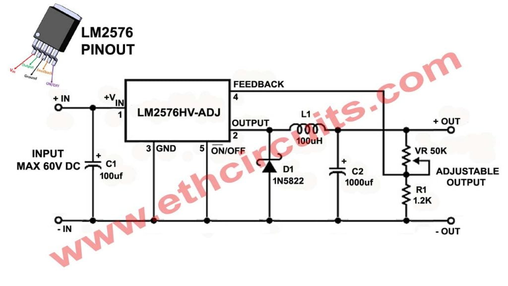
The LM2576 Is a Very useful regulator and low-cost integrated circuits that provide all the active functions for a step-down (buck) switching regulator. In This article I will explain about very easy buck converter circuit diagram ( dc to dc step down converter) The ICs are capable of driving a 3A load with excellent line and load regulation. The devices are available in both adjustable output and in fixed output voltage versions (3.3V, 5V, 12V and 15V).

The LM2576 requires only a minimum number of external components, in this buck converter we will use only 7 components. A standard series of inductors optimized for use with the IC are available from several different manufacturers. Because of the high efficiency of the switching regulator, the required size of the heat sink will be small and in some cases no heat sink is required.

The regulator will work with a wide input voltage range: up to 40V for the low voltage and up to 60V for the high voltage (HV) version. Other features: external TTL shutdown capability with 50 µA standby current, cycle-by-cycle current limiting and thermal shutdown for full protection under fault conditions.

Buck Converter Circuit Diagram

The circuit below is simple, easy to build and cost effective, Using the LM2576HVT-ADJ or LM2576HVS-ADJ adjustable version we can build a simple switching regulator with a 1.2-59V, 3A variable output from a 60V unregulated power supply. The maximum output current is 3A.

Click Here To Buy
buck converter circuit diagram, dc to dc step down converter circuit

Parts List for Dc To Dc Step Down Converter Circuit

  • IC:- LM2576HVT-ADJ or LM2576HVS-ADJ
  • L1:- 100µH 
  • D1:- 1N5822 (Schottky Diode)
  • C1:- 100µF/75V (electrolytic capacitor)
  • C2:- 1000µF/75V (electrolytic capacitor)
  • VR:- 50K potentiometer
  • R1:- 1.2K Resistor 1/4watt

Very easy Project to understand how Tesla Coil Works A Tesla coil is a type of resonant transformer circuit invented by Nikola Tesla around 1891. Read More……..

PCB Layout For Buck Converter Circuit

Just Download This Image and print it on a A4 size Paper no need to any adjustment in size or download gerber file from link below. How to use this print at Vero Board watch video for details. Use any colors of pcb print I have given you a print in 4 colors

dc to dc buck converter circuit diagram pcb layout

All Products are Suggested BY Me Please Check Above Link

Additional Features of LM2576

  • 3.3V, 5V, 12V, and adjustable output versions
  • Voltage over specified line and load conditions:                                                             Fixed version: ±3% max. output voltage                                                             Adjustable version: ±2% max. feedback voltage
  • Guaranteed 3A output current
  • Wide input voltage range: 4V to 40V With High Voltage IC Input 4V-60V
  • Wide output voltage range: 1.23V to 37V With High Voltage IC Input 4V-59V
  • Requires only 6 external components
  • 52kHz fixed frequency internal oscillator
  • Low power standby mode IQ typically < 200µA
  • 85% efficiency (adjustable version typically > 85%)
  • Uses readily available standard inductors
  • Thermal shutdown and current limit protection
  • Operating Temp Range  -40 to 125
  • 100% electrical thermal limit burn-in

How To make Buck Converter Circuit Watch Video

error: Content is protected !!
Scroll to Top