0-30V 0-10A Variable Power Supply Circuit Diagram | Adjustable Variable Power
In This Article I have given you a very simple 0-30V 0-10A Variable Power Supply Circuit Diagram | Adjustable Power Supply Circuit Diagram . With the help of this Circuit u can easily make a very cheaper Bench Power supply at your home. Every lab needs to be equipped with essential equipment. Out of all I would say power supply is most important since it powers up the projects.
Batteries, DC adapters can do fine job but as demand grows and project gets bigger a professional and adjustable power supply becomes a necessity.
To cater that I have designed an adjustable 0-30V 0-10A Regulated Variable power Supply circuit | 30v 10a power supply circuit with adjustable current limiting from 0A to 10A.
This is the Best Variable power supply Circuit Diagram. You can increase its output ampere just add more TIP3055 Transistor in parallel
0-30V 0-10A Variable Power Supply Circuit Diagram | Adjustable Variable Power
0 To 30V Variable Power Supply Circuit Working And Details
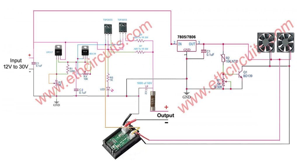
This is a 30v 10a power supply schematic that can provide output of 1.5v to 30v DC and current of 0 to 10A max. Use a 5k potentiometer to adjust the power supply and a 10k potentiometer with a BD139 transistor to adjust current power.
2 power Transistor 2N3055 | TIP3055 is used in this circuit to control the output current. Use the Appropriate heat sink to adjust both transistors because at high current transistors are hot. Also use a heat sink with LM317 regulator ic.
If you need a current limit of 5A at the output then use a 5A transformer. If you need a 10A use a 10A transformer or SMPS. The output current depends on the input transformer current. A 2amp transformer will not supply more than a current 2A.
The Bridge rectifier module is available in the market for 15A or different current ratings, you can use as per your transformer current. Adjust the circuit to the cabinet and both the potentiometer knob connected to the circuit should come out of the cabinet for adjust voltage and current.

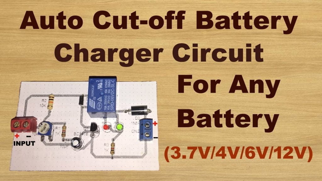
This battery charger circuit provides the Automatic cut off the facility when the battery gets fully charged.Before the use of this circuit, you need to adjust the Cut off voltage range for the auto cut.This adjustment is done by the 10k preset, and a multimeter connected with the output terminals that go to the battery. Continue Reading….
Parts List for 0-30V Variable Power Supply
- 1x LM 317 Regulator Integrated
- 2 x .1uf Capacitor
- 1 x 5K Potentiometer
- 1 x 10K Potentiometer
- 1 x 220R Resistor
- 1 x 1K Resistor
- 1 x 5mm LED
- 2 x 0.10R to 1R 5W Resistor
- 1 x 1000uF 35V Capacitor
- 1 x BD139 Transistor
- 2 x TIP3055 Power Transistor
- 2 x Aluminum Heatsink
Temperature Controlled Fan Circuit For 0-30V Variable Power Supply Circuit Diagram

PCB Layout for 0 to 30 volt variable power supply circuit diagram

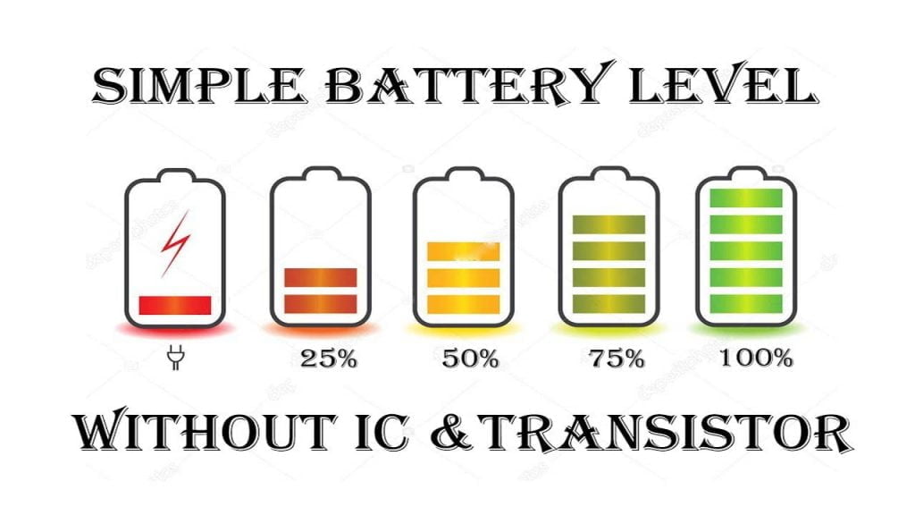
In this project, I will show you how to design a simple Battery Level Indicator Circuit using easily available components. Battery level indicator indicates the status of the battery just by glowing LED’s. This article explains you how Continue Reading…
All in one 0 to 30 volt variable power supply circuit diagram With Fan And Voltmeter


