What is Inductor | Inductor Symbol | Types of Inductors | Inductor Formula | Relative Magnetic Permeability
In this article I will try to explain everything about inductor:- what is inductor, inductor Symbol, Inductor Formula, Types of Inductor, Relative magnetic permeability, inductor uses, what is inductance and many other things about inductor
What is Inductor
The Inductor is perhaps the simplest of all electronic components, constructed much like a resistor – a simple length of wire that is coiled up. Inductors are typically found in a PCB assembly as they are an important part of an electrical structure.
However, here, resistance is not the property we’re looking for. It is something that happens because of the shape of the wire – a coil – it creates a magnetic field when a current is passed through it.
This induced magnetic field gives this bit of wire some interesting electrical properties, especially inductance – which gives these parts their name.
An Inductor, also called a coil, choke, or reactor,
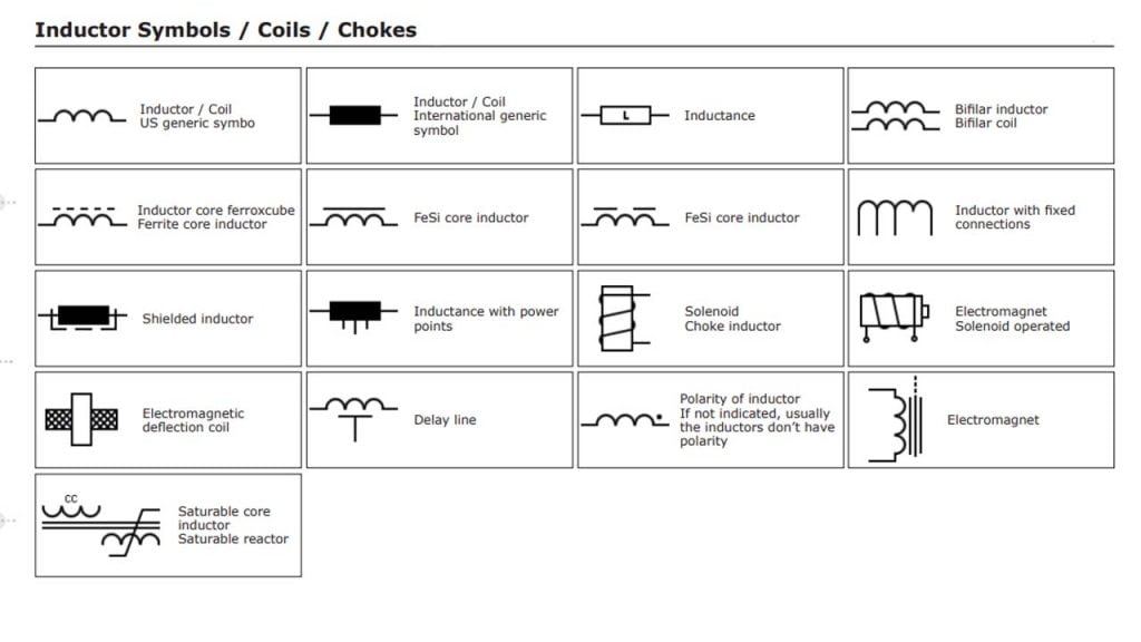
Inductor Symbol
Types of Inductor
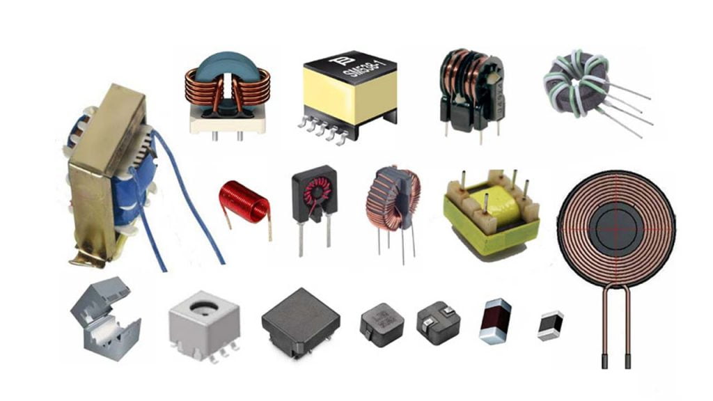
Depending on the application there are many types of inductors, they come in various form factors, there are high-frequency inductors, low-frequency power line inductors, and some specially designed inductors for decoupling and filter applications, below we will discuss different types of inductors in details. Below I am showing some types of Inductor
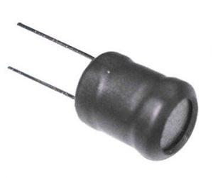
Iron Core Inductor
In the areas where low space inductors are in need then these iron core inductors are best option. These inductors have high power and high inductance value but limited in high frequency capacity. These are applicable in audio equipment’s. When compared with other core indictors these have very limited applications.
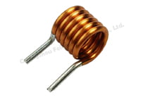
Air Core Inductor
By taking a cylindrical material of specific diameter (like a drill bit) as a template, we can wrap around a length of wire to make an air-core inductor, further the inductance can be stabilized by dipping the inductor in varnish or securing it by wax.
The core material is air, so it has low permeability hence lower inductance so, it can be used for high-frequency applications.
Ferrite Core Inductor

Mixing Iron oxide (Fe2O3) in combination with other metal oxides like (Mn), zinc(Zn) or magnesium(Mg) at a temperature of 1000° C – 1300° C will result in a material with very interesting magnetic properties called ferrite.
Ferrite core inductors have high permeability, high electrical resistivity and low eddy current losses these characteristics make them suitable for many high-frequency applications.
Bobbin Inductor
Winding a length of wire in a specially made cylindrical bobbin and securing it with a shrink tube forms a bobbin inductor.
The core material is ferrite so, the properties are also similar to a ferrite core inductor. The small size makes them suitable for power adapter like applications.
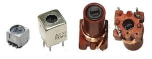
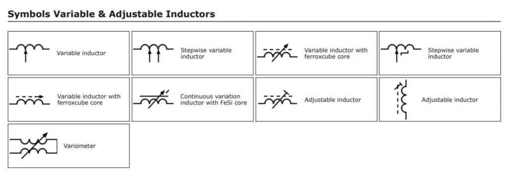
Variable Inductor
It is formed by moving the magnetic core in and outside of the inductor windings. By this magnetic core we can adjust the inductance value. When we consider a ferrite core inductor , by moving its core inside and outside on which the coil is wounded , variable ferrite core inductor can be formed.
These type of inductors are used in radio and high frequency applications where the tuning is required. These inductors are typically ranged from 10 μH to 100 μH and in present days these are ranged from 10nH to 100 mH.
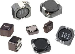
Shielded Surface Mount Inductor
It is built by winding a length of wire in a cylindrical bobbin and securing it in a specially made ferrite housing forms, shielded surface mount inductor.
These inductors are specially designed for PCB mounted applications and the shielding is there to reduce EMI and noise from the inductor and also to be able to use in a high-density design.
Toroidal Inductor
Wire wounded on core which has ring or donut shaped surface. These are generally made up of different materials like ferrite, powdered iron and tape wound etc. This inductor has high coupling results between winding and early saturation.
Its arrangement gives minimum loss in magnetic flux which helps to avoid coupling magnetic flux with other devices. It has high energy transferring efficiency and high inductance values at low frequency applications. These inductors mainly used in medical devices, switching regulators, air conditioners, refrigerators, telecommunications and musical instruments etc.
Multilayer Chip Inductors
The name itself indicates that it consists of multilayers. It is built by using thin plates made out of ferrite. The coil pattern is printed on it, with special metallic paste (recipe confidential to manufacturer), proper placement of these sheets a layer after another forms a coil hence inductance.
Inductance Prefixes
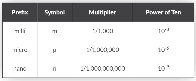
So to display the sub-units of the Henry we would use as an example:
- 1mH = 1 milli-Henry – which is equal to one thousandths (1/1000) of an Henry.
- 100μH = 100 micro-Henries – which is equal to 100 millionth’s (1/1,000,000) of a Henry.
There are many factors which determine the inductance of a coil such as the shape of the coil, the number of turns of the insulated wire, the number of layers of wire, the spacing between the turns, the permeability of the core material, the size or cross-sectional area of the core
How To Make Toroid Inductor | Toroid Inductor Formula | Inductor Calculator
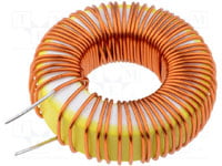
Toroidal coils on ferrite ring or rings of carbonyl iron powder are widely used in amateur radio designs. Their advantage is the high combined inductance with the small stray field. Calculation of the coil can be carried out in various ways.
The most used method for calculation is based on a special parameter AL. This parameter is usually included in the specification of the ferromagnetic rings and published by manufacturers. Numerical parameter AL is the inductance in uH at 100 turns of the coil for the iron powder ring or the inductance in mH at 1000 turns of the coil for the ferrite ring. Knowing the AL parameter, the number of windings of the toroid can be calculated using the following expressions:

The first formula for the iron powder ring,
The second formula for the ferrite ring.
The calculation in the Coil32 program is based on two empirical formulas. For the calculation by these formulas is enough to know the dimensions of the ring and its permeability.
 | at D1/D2>1.75 |
 | at D1/D2<1.75 |
All dimensions are in millimeters, the inductance in uH. μ is the relative magnetic permeability of the core. In the case of low-current inductors, you can assume it as initial magnetic permeability. These formulas are not applicable for power chokes calculation.
At the same time, by the numerical algorithm, the program calculates the length of wire needed for the winding. Wire length is calculated with a margin of 10 cm on the “ends”. If on finish you see string:” Coil cannot be realized!”, it means that the wire cannot be placed in the inner diameter of the ferromagnetic ring and you must decrease the diameter of a wire.
Online Calculators
Calculating characteristics of an unknown toroid
Information about Iron Powder Toroid
Information about Ferrite Toroid
Relative magnetic permeability of Common Toroid


