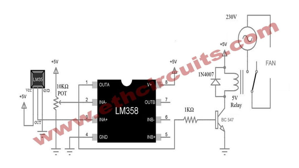
The picture shown below is a basic Temperature Controlled fan Circuit utilizing LM35 Temperature Sensor, LM358 Op Amp, and a 5V Relay Module.
Let me start describing the design of the Temperature Control Switch circuit with the Op-Amp LM358. Pins 8 and 4 (V+ and GND) of LM358 are connected to +5V and GND.
Since LM358 is a dual op-amp IC, you can use either of the Op Amps. Pins 1, 2, and 3 are associated with one ap amp and pins 5, 6, and 7 with the other. I will be using the first op-amp i.e. pins 1 (OUT), 2 (INA-) and 3 (INA+).
Now, connect the Centre terminal of the 10KΩ Potentiometer to Pin 2 of LM358 (the other terminals of the POT are connected to +5V and GND). Pin 3 of LM358 is connected to the OUT Pin of LM35 Temperature Sensor. The other two pins of the LM35 IC are connected to +5V and GND you can see in diagram.