will see that the Digital dice circuit separated are 3 main section. There are the frequencies generator, the frequencies counter and LED display. In the frequencies counter With IC555 are set as high frequencies generator.
Then, will be a normally open pushbutton to connects signal from the first sector to second sector. By the frequency counter which is used as CD4017 is the counter.
Normally this IC number will be Decade counter with 10 decoded outputs IC. But in this IC we joint pin 5 and 15 together. Now only 6 output will work (Output Pin 3,2,4,7,10,1).
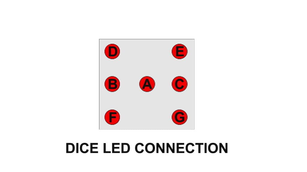
Every time that we press Push Switch. Next, IC2 will change the output position. The matrix diode act as the divider output signal of IC to each place of LEDs since 1 to 6 LEDs. But why use 7 LEDs, because the position of the LED dice like that.
Especially at the 1, 3, 5 pts. If use LED just 6 LED only will cause LED is not the centre does not look beautiful, so I added another one.you will easily make your digital dice circuit using ic 4017 with the help of the above circuit.