Simple DC To DC Voltage Booster Circuit Diagram

A Step-up circuit receives a lower voltage and produces a higher Output to be used where that higher voltage is not available. DC To DC Voltage Booster Circuit have lots of uses with most common on battery operated applications.

This is a Simple DC To DC Voltage Booster Circuit . The Input voltage can be as low as 1 V – 1.5V DC and can provide 20VDC Output.

DC To DC Voltage Booster Circuit Diagram 1.5 V To 20 V

Click Here To Buy
DC to DC Voltage Booster circuit diagram

It requires only a few external components. The IC consists of many good features and functions. Built inside its circuitry which are, built-in 3A NPN switch at output,52 kHz oscillator, current limit function, Continue Reading….

Parts List:

  1. Transister 2n2222 , 
  2. Diode IN4007 ,
  3. Resistor 47 ohm ,
  4. Toroid from Old CFL ,
  5.  1mm (18AWG) insulated copper wire , Please see full video for detail

How Circuit Works

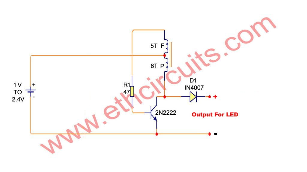
Here is an interesting circuit of 1.5 V to 20 V converter Circuit  from an ordinary 1.5V AA sized cell. At the heart of this circuit is transistor 2n2222 you can use S9013. 

This charger circuit will step up the voltage from 1.5V to 5V DC. The circuit uses only an AA or AAA 1.5v battery (1V to 2.4V).  The charger is composed of simple oscillator, a rectifier, and voltage regulator. 

The feedback winding F is composed 5 turns of #30 AWG magnetic wire and main winding P is composed of 6 turns of #24 AWG wire. 

The windings are not critical, and you can experiment using different number of turns. If ever the charger doesn’t have any output, try to reverse the winding connection.


How To Make Voltage Booster Circuit Watch The Video

error: Content is protected !!
Scroll to Top