What is BMS Circuit ( Battery Management System Lithium ion)
Battery management systems may be as simple as electronics to measure voltage and stop charging when the desired voltage is reached. At that point, they might shut down the power flow; in the event of irregular or dangerous conditions they might issue an alarm.
Lithium-ion batteries are now very popular. Now-a-Days these batteries are used in maximum devices. But unlike other types of batteries, for example, lead-acid or nickel batteries, lithium-ion batteries are very demanding for the charger parameters. Battery management system lithium ion batteries (Like 18650 Batteries) is very important.
If you don’t control the process of charging and discharging of Lithium-ion batteries, they will fail soon. These batteries can swell and even explode from overcharging, and a deep discharge can cause of battery failure.
The ideal charger for lithium-ion batteries should have a stabilizing unit for voltage and current and also a voltage balancing system for banks. The voltage of the fully charged can of lithium-ion the battery is 4.2 Volts.
As soon as the battery has reached this voltage, the charging process should stop. Today we will examine a circuit that will allow charging lithium-ion cans connected in series, as well as balancing them in the process of charging. This circuit is not only simple but also very effective.
3S DIY BMS Circuit Diagram or Battery Management System Lithium ion Batteries Working
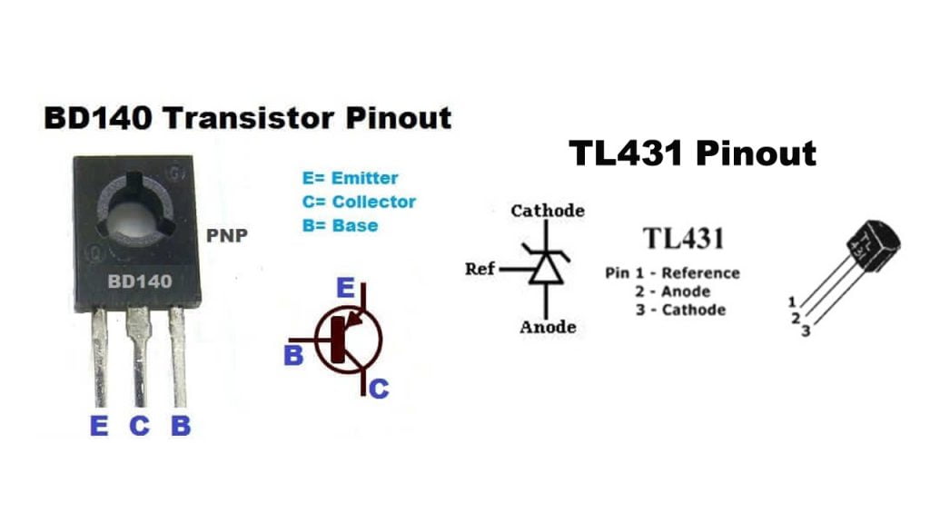
The circuit consists of a regulated Zener the diode on the basis of the chip TL431. At a given voltage, a power transistor opens. With the 10 Ohm 1-2 Watt Resistor in the collector circuit, it forms the equivalent of the load .That is, the excess power will be dissipated as heat on these elements, So the transistor need a heat sink.
In This Circuit I used PNP Transistor BD140 . You can Use any PNP transistor with a collector current above 1 Ampere. On 1 board I collected 3 similar circuits. This assembly will help to charge 3 lithium-ion batteries at once.
You Can make 3s-4s-5s etc… circuit with the help of this circuit the number of assemblies can be anything. The board has a tuning resistor to adjust the circuit for the desired cut out voltage .The LED indicator on the collector circuit of the transistor will glow when the transistor is open, thereby indicating that the charging process is complete.
Battery Management System BMS Circuit Diagram


Parts List For Battery Management System ( BMS For 18650 ) Circuit
- Regulated Zener Diode TL431 3pc
- Transistor BD140 3pc
- LED 5mm 3pc
- Resistor 20k 3pc, 10k 3pc, 1k 3pc, 150 ohm 3pc all 1/4watt
- Resistor 10 ohm 1-2watt 3pc
- Variable Resistor 10K 3pc
- Vero Board
Adjustment of The BMS Circuit (3.7V Battery)
Adjustment of the circuit is a simple. Set the voltage in the region of 4.2 Volts on Bench power supply (Circuit Here) .Then connect the board to it and slowly rotate the trimmer until the LED illuminates.
Adjust all balancing units so that the current consumption or balancing current for all was the same . For the most accurate setting, I advise you to use multi-turn trimmer resistors. Naturally, there are programs for calculating the chip of the TL431. But in any case, the resistors have a spread, so all the units require an individual adjustment .
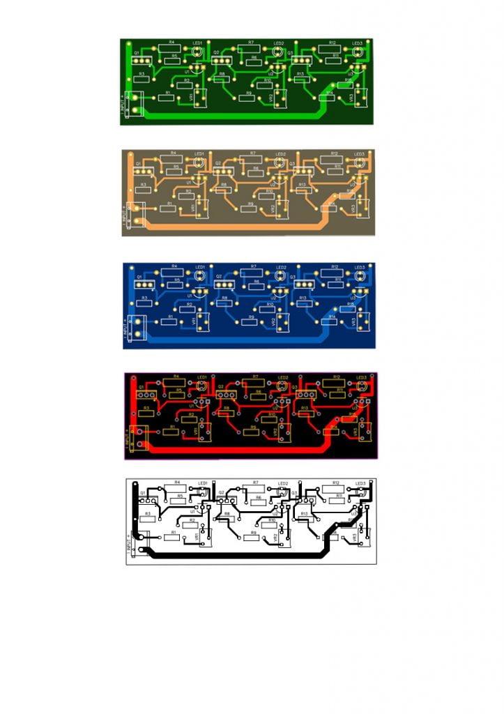
Updated PCB Layout For Battery Management System
I updated this PCB Layout please follow this PCB Layout. Download This layout from Link or save from this image below and print it on A4 Size paper no need to any adjustment in paper or image size. Download Gerber File From Link Below

