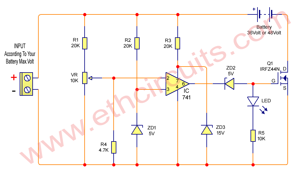
As shown in the circuit diagram, the main element in the circuit is the opamp IC 741, which is listed as a comparator.
Pin # 3 which is a flexible IC input refers to a 5V fixed voltage with the following zener ZD1 / resistor R2 network.
Other inputs used with sensor voltage are actually the combined voltage from the supply and from the battery, in other words the charging voltage used in the battery for charging.
The resistance pin in pin # 2 and the pre-set form a voltage separator that is initially adjusted so that the voltage at this pin stays below the voltage level in pin3, which is the reference voltage set to 5v by the zener diode.
The preset is set in such a way that the voltage at pin # 2 rises above the 5V mark as soon as the electrical power of the battery rises above the battery level limit.
When this happens, the output of the opamp to the ground is turned off mosfet, and disconnects the voltage to the battery.
Initially as the battery voltage and maximum power output from the Input supply Voltage remain below the full charge level of the battery, the opamp output remains high and our mosfet remains ON.
This allows the battery voltage to be charged, until the above limit is reached which automatically prevents the battery from charging.
Mosfet can be selected according to AH battery level.